Relay 12 Volt Wiring Diagram

19 Awesome 12V Relay Wiring Diagram
The 12V Relay Diagram is an essential device for controlling electric current in a wide range of applications. By connecting a 12V relay switch to a battery, voltage regulator, and other components, you can easily control the flow of electricity in almost any electrical system. The 12V Relay Diagram works by using two separate circuits.
Relay 12 Volt Wiring Diagram
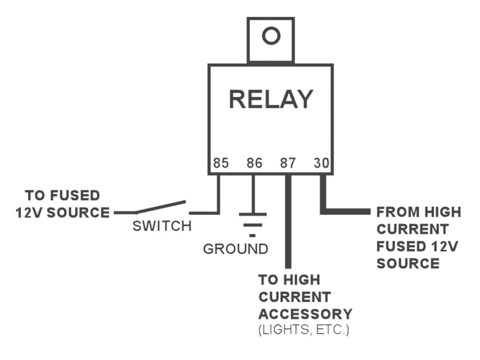
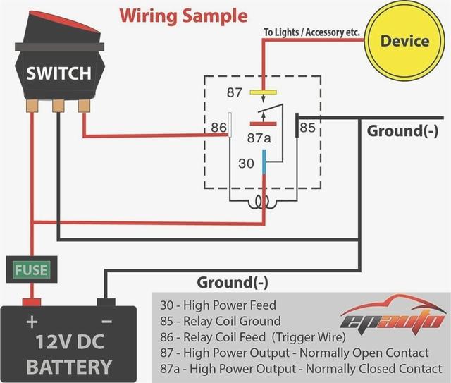
Wire the relay's terminals according to the wiring diagram, considering the available pins, markings, and the circuit's purpose. Connect the 12V power source to Pin 30. Connect the (trigger) control circuit to pins 85 and 86. Connect the load (you want to control) to Pin 87 to be normally open when the relay is active.
12V Relay Wiring Diagram 5 Pin Cadician's Blog
Understanding 12v 30 Amp Relay Wiring Diagrams for a Professional InstallationRelay wiring diagrams are an essential tool when installing electrical components. They provide a visual representation of the connections between the various components and allow for quicker and more accurate installation. This is especially true for 12v 30 Amp Relay Wiring Diagrams, which are used in a wide.
Wiring Diagram For Relay
A 12V relay diagram is an essential tool for any car or home electronics enthusiast. It provides a clear and concise way to understand the electrical components of any wiring system, allowing for quick diagnosis and repair. The 12V relay diagram consists of two main parts. The first part is the power source, usually a 12V battery.

5 Pin Relay Wiring Diagram Wiring Electrical diagram, Relay
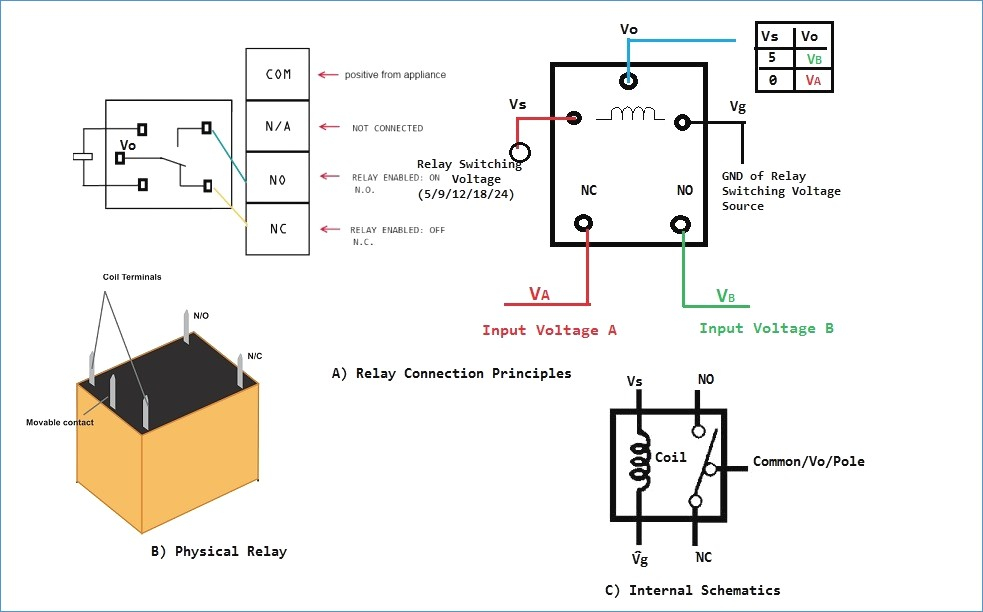
5-Pin-Relay-Wiring-Diagram-On-Relay-Case. According to DIN 72552 Standard, each pin of a relay is numbered 85, 86, 30, 87, and 87a. You need to know that a relay has two circuits, a coil circuit (also called a "low current circuit", or "inductive circuit"), and a high-amperage circuit. In a relay 85 and 86 pins are considered coil.
12 Volt Spotlight Wiring Diagram Diagram Database
20. Door Locks - Nissan Maxima 1995 - 1997, Double Ground Pulse Relay Diagram. 21. Door Locks - Nissan's Single Wire '91-'95 using 1 relay and 1 diode (Type F) 22. Door Locks - Nissan's Single Wire '91-'95 using 2 relays (Type F) 23. Door Locks - Single Pulse to Lock and Unlock - Negative Pulse. 24.
relay wiring MG Midget Forum The MG Experience
The Bosch relay 12v 30a wiring diagram is a vital tool for understanding and implementing the proper wiring connections for this type of relay. Bosch relays are widely used across various industries and applications, including automotive, marine, and industrial sectors. This guide aims to provide a comprehensive overview of the wiring diagram.

Hollie Wires Wiring Diagram A 12 Volt Automotive Relay
A 12 volt relay module is a device that uses a small electrical current to remotely control larger currents and voltages. It is used in many different applications, from home automation and lighting control to automotive power management. The most common form of a 12 volt relay module circuit diagram is a series of interconnected rectangles.

12 Volt Latching Relay Wiring Diagram / 12 Volt Latching Relay Wiring
It is commonly used for controlling lights, fans, motors, and other electrical devices that require a higher current to operate. When wiring a 12 volt relay, it is important to follow the schematic diagram provided by the manufacturer. This diagram shows the connections and components required to properly control the relay.

5 Pin Led Flasher Relay Wiring Diagram Wiring Diagram
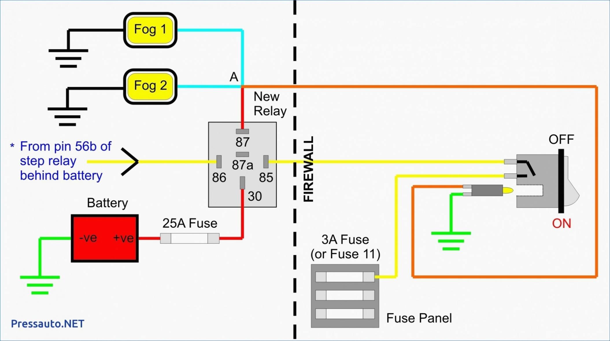
The above diagram is for relay triggering circuit. Since the relay has 12V trigger voltage we have used a +12V DC supply to one end of the coil and the other end to ground through a switch. For switching we are using a transistor as a switching device. You can also notice a diode connected across the coil of the relay, this diode is called the.

How to use this 12V Relay with Optocoupler? Page 2
QUICK TIP: This is a portion of my larger "Relays Explained" video. In this quick tip we look at how to wire a 12V Automotive Relay.See the full video here:.

12 Volt Relay Wiring Diagram Free Wiring Diagram
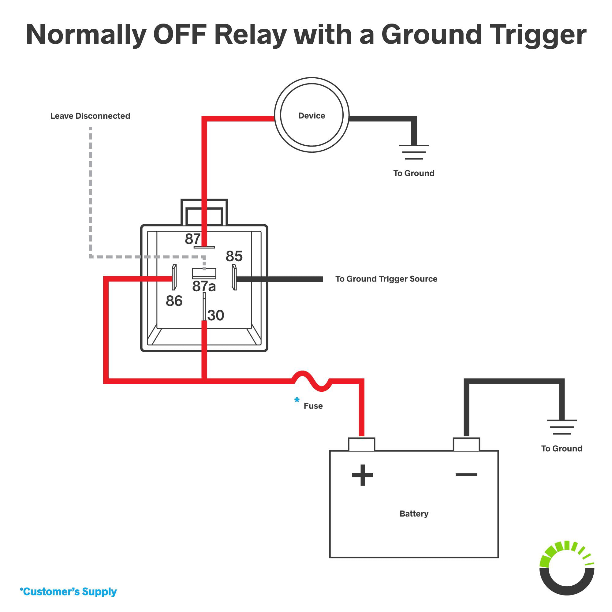
Four-pin relays are commonly used in the application of fog lights, LED lights, and automotive electronics. Wiring a four-pin relay is a simple three-step process: Connect a 12V battery to Pin 30 of the relay via fuse. Connect Pin 85 to the ground.
55 12 Volt 40 Amp Relay Wiring Diagram Wiring Diagram Harness
Now that you understand the basics of 12v relay wiring, it's time to look at how to construct a wiring diagram. Most 12v relays will have four pins arranged in a row on the bottom of the unit. The pins are often labeled as "NC" (normally closed), "NO" (normally open), "COM" (common) and "VCC" (power). To properly wire a 12v.

5 Pin Relay Wiring Diagram Use Of Relay
A 12 volt relay wiring diagram is an essential tool for any electrician or automotive enthusiast. It's important to know how these diagrams work before attempting to wire up your own relay. When wiring a 12 volt relay, there are several points to keep in mind. First, the diagram should include a power source, such as a battery, which will.

12v Relay Wiring Diagram Spotlights Free Wiring Diagram
Connect the Coil + pin to one side of a power switch or a control circuit that provides a 12v signal to activate the relay. Connect the Coil - pin to the ground or negative side of the power supply. This completes the control circuit for the relay. In some cases, an additional pin labeled A1 may be present.

Best Bosch Relay Wiring Diagram 5 Pole • Electrical Outlet Symbol 2018
Subwoofer Wiring Wizard - Easy to understand diagrams of one to four speakers with a variety of single and dual voice coils. Vehicle Wiring - Our free vehicle wiring section includes car alarm wiring, remote start wiring, car stereo wiring, cruise control wiring, navigation wiring, and more for most vehicles available in the U.S. as early as.
